
REVISION of EMI and AC
Magnetic Flux
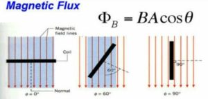
Magnetic flux through a plane of area dA placed in a uniform magnetic field B, Φ = ∫ B.dA,
If the surface is closed, then, Φ = 0
This is because magnetic lines of force are closed lines and free magnetic, poles do not exist.
Electromagnetic Induction: Faraday’s Law
a). First Law: whenever there is a change in the magnetic flux linked with a circuit with time, an induced emf is produced in the circuit which lasts as long as the change in magnetic flux continues.
b). Second Law: Induced emf, ε = dΦ/dt
Lenz’s Law
The direction of the induced emf or current in the circuit is such that it opposes the cause due to which it is produced, so that, ε = -NdΦ/dt, N is No. of turns in coil
Lenz’s law is based on energy conservation.
EMF Current and Charge Induced in the Circuit
Charge depends only on net change in flux does not depends on time.
Emf Induced Due to Linear Motion of a Conducting Rod in a Uniform Magnetic Field
E = –L.(v × B), If L, v and B are perpendicular to each other E = BvL
Induced EMF Due to Rotation of a Conducting Rod in a Uniform Magnetic Field
E = BLω²/2 = BAn
Where n is the frequency of rotation of the conducting rod Induced EMF Due to Rotation of a Metallic Disc in a Uniform Magnetic Field
E = BLω²/2 = BAn
Induced EMF, Current and Energy Conservation in a Rectangular Loop Moving in a Non – Uniform Magnetic Field with a Constant Velocity
Transformer
Working on the principle of Mutual Induction,
Device, that changes the magnitude of alternating voltage or current. The voltage or current is fed into primary coil and taken from secondary coil.
If it increases the voltage, it is termed as STEP UP transformer, but consequently it will reduce the current.
Ratio of coils is termed as transformation or transfer ratio
![]()
For ideal transformer Pinput = Poutput ; EPIP = ESIS
For STEPUP NS > NP
Efficiency = OUTPUT/INPUT
GENERATOR converts Any energy (Mechanical/Hydo/Nuclear/Thermal etc) to convert to electrical energy
Values of Alternating Current and Voltage
- Instantaneous value: It is the value of alternating current and voltage at an instant t.
- Peak value: Maximum values of voltage E0 and current I0 in a cycle, are called peak values.
- Mean value: For complete cycle is ZERO, For HALF CYCLE EMEAN = 0.636 E0
- Root – mean- square (rms) value: ERMS = 0.707 E0
Phase difference Between the EMF (Voltage) and the Current in an AC Circuit
- For pure resistance: The voltage and the current are in same phase i.e. phase difference Φ = 0
- For pure inductance: The voltage is ahead of current by 90 OR π/2 e. phase difference Φ = π/2.
- For pure capacitance: The voltage lags behind the current by 90 OR π/2 i.e. phase difference
Φ = -π/2.
ROLE of CURRENT ELEMENTS, Resistance, Inductor and Capacitance in AC currents
RESISTANCE has SAME role in AC as well as DC to stop/ create obstruction in flow of current. The obstruction offered does not depend on the frequency of AC
INDUCTOR has ZERO Resistance to flow of current in DC but offers obstruction in AC, and obstruction depends on frequency of AC as well. The resistance offered by it is NOT termed as resistance but REACTANCE ( Differ in AC and DC), The reactance is given as XL = ωL.
Unit of XL is OHM only. For all practical purposes of your syllabus, it is just as resistance but only DIFFERENCE that it depends on FREQUENCY, For DC circuit as ω is ZERO i.e. XL = 0
CAPACITOR has INFINITE Resistance to flow of current in DC but offers obstruction in AC, and obstruction depends on frequency of AC as well. The resistance offered by it is NOT termed as resistance but REACTANCE ( Differ in AC and DC), The reactance is given as XC = 1/ωC.
Unit of XC is OHM only. For all practical purposes of your syllabus, it is just as resistance but only DIFFERENCE that it depends on FREQUENCY, For DC circuit as ω is ZERO i.e. XC is INFINITE
SERIES LCR CIRCUIT
IMPEDANCE is defined as the net OBSTRUCTION to flow of current in AC
RESONANCE is a very special phenomenon in AC CIRCUIT
At resonance
VL = VC
Z = R
XL = XC
f = 0
Z is MINIMUM
I is MAXIMUM
These all CONDITIONS are interdependent.
POWER IN AN AC CIRCUIT
Now as the Formula for power is P = VI = EI, Also E and I are both Sine/Cosine functions. Every cycle they touch zero at least TWICE, and value keeps on changing regularly for instantaneous value.
The product P = VI also varies continuously.
TAKE COMPLETE NOTES HERE
So we don’t define instantaneous Power in circuit, and we define and calculate the AVERAGE POWER for a cycle.
PAVG = EvIv cos Φ
Where this Φ is same PHASE ANGLE.
For PURE inductor and Capacitor, POWER consumed is ZERO.
RESISTANCE CONSUMES MAXIMUM POWER
Wattless Current
The component of current differing in phase by π/2 relative to the voltage, is called wattles current. CONCEPT of WATTLESS current is used in decreasing Voltage without loss of ENERGY in AC only.
QUALITY FACTOR
It is defined as the ratio of voltage across Capacitor or Inductor at RESONANCE) (BOTH are same) to that across Resistance
At last we must see previous years PAPERS and Questions from NEET